Original portuuese version here!

segunda-feira, 19 de setembro de 2011

A New Heated Bed


During the last few weekends Jorge L., Luis Viola and I (Alain Mouette) were working in the Lab finishing the assembly of the Heated Bed among other things.


  • Measurements that we made
The measurements had already been made ​​and are documented in 11/julho Blog . I am repeating here the important results:
  • Dimensions: 145 x 196 x 5 mm aluminum
  • First, we connected it to a smaller Power Supply that only provided 3A and 7.1 V (with smaller resistors) the temperature stabilized at 58.5°C at 20°C ambient temperature. So we have a dissipation constant (58,5-20)/(3*7.1) = 1.8°C/Watt.
  • To achieve higher temperatures, 110°C or more, as Nophead is using , we will need (110°C-15°C)*1.8 = 52W only for losses to the environment.
  • Heating rate: we let it cool down and fed it with a bigger Power Supply, with 50W. It warmed up from 24°C to 52.5°C in 410s ie: (53.5-24)/410 = 0.07 ° C / sec.
  • We designed a total power of 150 watts, it should be ok for a PC power supply.

  • Assembly
The test resistors were replaced with larger resistors. Each resistor is 10 Watts (cost $1.00), glued to the table below with epoxy adhesive (Araldite). Each of 6R8 with 12 Volts dissipates around 20W, being fixed in a huge heatsink, they can function properly.

The total power of 150 Watts achieves 60°C in 3 minutes and 110°C in 5 minutes. After heating consumes approx. 50W to maintain 110°C.


The temperature sensor was fixed later. It is reasonably close to the center of the plate and just a little closer to the home position where we print most of the pieces.

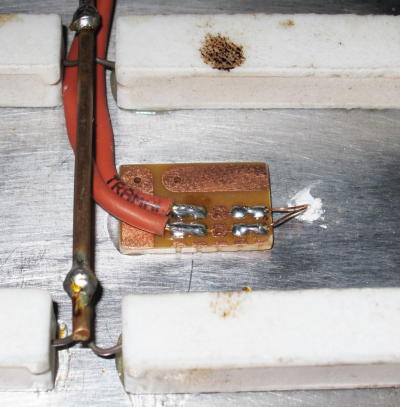
The plate is glued with epoxy adhesive. Jorge made a small blind hole filled with thermal paste where the sensor was
inserted.

We used the Murata Thermistor 100k 1% found at Mouser for $ 0.79 .

  • Electronics
I mounted a small driver with a MOSFET that is able to withstand that much current: IRFZ48 that cost only $1.10.

I have used a TC4427 driver because the MOSFET is driven under 12V, it was found at Farnell.
(Click to enlarge the schematic)
This board is the prototype driver. The power tracks are reinforced with solid wire on the back side.

As we are using a PC PSU, I used the 4 wire 12V connector that goes to the motherboard.

The heatsink is 25°C/W a little too small. The MOSFET voltage drop (Rdson=17mOhms) was measured as 0.2 V generating 2.5 W during cold-start.
That heatsink got too hot, so I made a quick modification. This got a little cooler than necessary so it is ok.

According to the datasheet, the thermal resistance should be 15°C/W.
The input was designed for connecting directly the micro-controller I/O pin, so we needed to make a connection at the entrance of the MOSFET on the extruder board.

  • Problems and Solutions
One problem that we had was that the Power Supply exploded! This is literally speaking, it was an unbranded PSU that had already provided many years of good service but a real load of 150W was more then it could take. Fortunately, Jorge found a similar PSU from Dell with the same specifications and is now working perfectly.

We aim to make another version powered directly from 110/220V AC power. This is more worrisome and for security reasons, I personally think it can be done on a glass plate instead of aluminum.

The functional outcome was very good, we did a lot of printing at 120 ° C and warping previously found almost completely disappeared. We still need tp test with larger pieces, will will see how it behaves in the future.

terça-feira, 8 de março de 2011

New Extruder Nozzle - Atibaia

This Sunday was very interesting, I went to visit Fabio Gilii at Atibaia and we made a new tip! Well, he did :)

First, interesting news: the ABS filament finally arrived! A nice 5 lb package, bought in the 3D-ink . I don't know other plastics in detail, but it is quite smooth and has a diameter of 2.85 mm. This material is missing from most vendors, so we only found it in black ...
Milling machining parts in is much more laborious and time consuming than I thought, we started right after lunch and ended late at night.

First we did the heater block, it took several hours ... We made 2 of them so that we have an extra one for other experiments.

Heater block (click to enlarge)
The block looks great! I redesigned it by copying all ideas from Adrian, here .

We simplified the threads, which became smooth with tight fitting with an M3 screw. 100% approved, it not only easier to manufacture but it was easyest to mount, dismount and adjust in position.

It was also "Tropicalized" (coloquial expression when adapting a projetc), a 6R8 5W resistor is easier to find (bought at Ohmega ), and thermistor has a hole with a wider part to the isolation of "Spaghetti fiberglass (bought at Casa Ferreira ). The high temperature adhesive Kapton came directly from China: High Temperature Tape .
The thermistor was purchased in Mendel-parts .

Then we did the nozzle of the extruder ...

The drill of 0.5 mm is so thin that it was necessary to realign the lathe and yet it was still critical. At one point I saw the bit folding and Fabio was able to take it out without breaking! This is not for everyone.
After a lot of work (only by Fabio), a bill that I at least thought it was beautiful.
We also made a new block of Teflon (not shown). The block of wood (Maçaranduba) was slightly modified. Each piece was adjusted on the previous one, so everything fits perfectly.


New Tip of the extruder mounted (click to enlarge)
Assembling everything, it was a great set, the block heater is very convenient to mount.

An interesting aspect of this project is that the heating occurs at exactly the desired point.

The resistor being farther away pruduces a more stable temperature because the fluctuations are reduced by the body of the block.

It is not helpful to have many resistors, just one with power enough to do the job. It is interesting to be able to better direct heat.


The new Tip m was largely copied from the last Adrian . Very important detail: it has the same diameter in brass and PTFE: 3mm! (not really a good thing)

PTFE now enters into the brass, it minimizes the problem of expansion of PTFE with the high pressure and temperature. Still a bit of plastic (5mm) melts in the reagion imediatly out of brass piece.

The strength of the extrusion is now exercised throughout a block of support, has improved significantly. In the original material is high temperature resistant, PEEK, but the wood worked perfectly: do not worry, do not deform and will not burn.

The block heater can be adjusted, it should be very close to the nozzle tip. The hole of the thermistor takes the temperature in the middle of the block, opposite the resistor.

Complete design: BicoExtruder01.pdf

Are we connect everything and it worked ... how wonderful!

But we still have problems:
  • The plastic tractor is slipping, it seems that the teeth are very shallow.
  • The engine is weak, sometimes fails. It needs a little manual help. Even increasing the voltage to 18V in the engine.
  • The two problems above are independent and add up: it sleeps even when pushing by hand.
  • We have an engine of 4.5kgf.cm NEMA17 kgf.cm the Masmorra (meeting point) ...
  • The PID Temperature Control leaves much to be desired, Gil Pinheiro work with this and has helped me understand what is wrong. Soon we will have a better system for now is good enough to continue testing.
 Other considerations:
  • support between the PTFE and the brass was made plan to distribute the pressure better, but still there was some deformation. Perhaps the original option of using a thread to improve this aspect.
  • Antonio Santos had passed this link on making a strengthening of copper around the PTFE. This new geometry improves the problem, but it showed me that even then there is an expansion of about 5mm in length. I will do more tests when we have a stronger engine.
NT: Translated by the author, from here.

    quinta-feira, 3 de março de 2011

    New Tractor for a Wade Extruder

    I got a new tractor for the Wade extruder, it seems like a progress, I don't know if it's the ultimate solution. The reasons for improvement are simple:
    • I used a screw with common steel (SAE 1020 steel) instead of a super-duper-bolt. For that I used a Capscrew 5 / 16 "x 2 1 / 2" that has no thread in the middle. Dimensions are almost equal (7.94 x 8mm)
    • I used a 6mm Tool. it gave me teeth twice larger and deeper, the traction got better because of this.
    • I used a crude method for manufacturing and thus the shape of the teeth still not perfect. I think a version made with proper tools could be much better
     I held the bolt in a vise with two bearings, one is bound by two screws and the other is loose, two pieces of softwood avoid destroying the bearings. The screw turns freely.

    The washers and a nut on the right serve as guide and adjustment of position and dispense the previous slot. With the drill at low speed, so the screw begins to rotate under the effect of the thread.
    The teeth are formed quickly.
    A little trim, or even the bearing will not come out any more ...
    Beautiful ...
    Mounted in place. The alignment is not perfect, it would take several washers thicknesses to fine tune.


    And finally you can see that the tractor marks in the plastic are much deeper than before. We'll see how it behaves in practice ...